Verilog Code Examples with Testbench
Introduction
This blog covers fundamental Verilog code examples with testbenche to make digital circuits understandable in an illustrative manner.
They include basic combinational circuits such as AND, OR, XOR gates, full adders, half adders, 2X1 multiplexers, and sequential circuits such as D latche, D flip-flop, and T flip-flop, ounter, etc. Every example includes a testbench to verify how the circuit functions and whether it is properly functioning or not.
These examples give a hands-on experience to digital design, hence making it simpler to implement concepts in FPGA development, ASIC design, and logic circuit projects.
Note: If you’re a beginner to Verilog, reading What is Verilog and Its Uses might be useful before you proceed with these examples.
Table of Contents
Basic Examples
Basic Display
module main;
 initial
  begin
   $display("Learning Verilog is easy with AyrElectrika");
   $finish ;
  end
endmodule
Combinational Circuits
AND Gate
Design File
module andgate (a, b, y);
 input a, b;
 output y;
  assign y = a & b;
endmodule
Testbench File
module andgate_tb;
wire t_y;
reg t_a, t_b;
andgate my_gate( .a(t_a), .b(t_b), .y(t_y) );

initial
begin
$monitor(t_a, t_b, t_y);
t_a = 1'b0;
t_b = 1'b0;
#5
t_a = 1'b0;
t_b = 1'b1;
#5
t_a = 1'b1;
t_b = 1'b0;
#5
t_a = 1'b1;
t_b = 1'b1;
end

endmodule
OR Gate
Design File
module or_gate(
 input a,b,
 output reg  y);
    always @(a,b)
    y = a |b;
endmodule
Testbench File
module tb_and_gate;
reg A,B;
wire Y;
or_gate a1 (.a(A) ,.b(B),.y(Y));

initial begin
    A =1'b0;
    B= 1'b0;
    #45 $finish;
end

always #6 A =~A;
always #3 B =~B;
always @(Y)
$display( "time =%0t \tINPUT VALUES: \t A=%b B =%b \t output value Y =%b",$time,A,B,Y);
XOR Gate
Design File
module xor_gate (
input a,b,
output y);
   xor x1(y, a, b);
//xor is a built in primitive. While using these primitives you should follow the connection rules.
//First signal should be output and then inputs.
endmodule
Testbench File
module tb_xor_gate;
    reg A,B;
    wire Y;
    xor_gate a1 (.a(A) ,.b(B),.y(Y));

    initial begin
        A =1'b0;
        B= 1'b0;
        #45 $finish;
    end

    always #6 A =~A;
    always #3 B =~B;
    always @(Y)
    $display( "time =%0t \tINPUT VALUES: \t A=%b B =%b \t output value Y =%b",$time,A,B,Y);

endmodule
Half Adder
Design File
module half_adder(
input a,b,
output sum,carry);
   assign sum = a^b;
   assign carry = a & b;
endmodule
Testbench File
module tb_half_adder;

    reg A,B;
    wire SUM,CARRY;

    half_adder HA (.a(A) ,.b(B),.sum(SUM),.carry(CARRY))

    initial begin
        A =1'b0;
        B= 1'b0;
        #45 $finish;
    end

    always #6 A =~A;
    always #3 B =~B;

    always @(SUM,CARRY)
    $display( "time =%0t \tINPUT VALUES: \t A=%b B =%b \t output value SUM =%b CARRY =%b ",$time,A,B,SUM,CARRY);

endmodule
Full Adder
Design File
module full_adder(
input a,b,cin,
output reg  sum,cout);

   always @(*) begin
       sum = a^b^cin;
       cout = (a&b)+(b&cin)+(cin&a);
   end

endmodule
Testbench File
module tb_full_adder;

     reg A,B,CIN;
     wire SUM,COUT;

     full_adder FA (.a(A) ,.b(B),.sum(SUM),.cin(CIN),.cout(COUT));

     initial begin
         A =1'b0;
         B= 1'b0;
         CIN = 1'b0;
         #45 $finish;
     end

     always #6 A =~A;
     always #3 B =~B;
     always #12 CIN = ~CIN;

     always @(SUM,COUT)
     $display( "time =%0t \tINPUT VALUES: \t A =%b B =%b CIN =%b \t output value SUM
      =%b COUT =%b ",$time,A,B,CIN,SUM,COUT);

endmodule
2X1 Multiplexer
Design File
module Mux2_1(out,cntrl,in1,in2);
  input cntrl,in1,in2;
  output out;
    assign out = cntrl ? in1 : in2;
endmodule
Testbench File
module mux2tb;
wire out;
reg cntrl,in1,in2;
Mux2_1 uut(out,cntrl,in1,in2);

initial
begin
     $monitor($time," out=%b,cntrl=%b,in1=%b,in2=%b",out,cntrl,in1,in2);
	cntrl=0;in1=0;in2=0;
     #1 in1=1;in2=0;
     #1 in1=0;in2=1;
	 #1 in1=1; in2=1;
     #1 cntrl=1;
     #1 in1=0;in2=0;
     #1 in1=1;in2=0;
     #1 in1=0;in2=1;
	 #1 in1=1; in2=1;
     #10 $finish;
end

endmodule
Sequential Circuits
D Latch
Design File
module d_latch(
input en,d,
output reg q);

   always@(en,d)
   begin
      if(en)
      q <= d;
   end

endmodule
Testbench File
module tb_latch;
    reg en,d;
    wire q;

    d_latch DLATCH (.en(en) ,.d(d) ,.q(q));

    initial begin
        en =1'b0;
        d =1'b1;
        #45 $finish;
    end

    always #6 en =~ en;
    always #3 d =~d;

    always@( q , en )
        $display("time =%0t \t INPUT VALUES \t en =%b d =%b \t OUTPUT VALUES q=%b",$time,en,d,q);

endmodule
D-FlipFlop(Asynchronous Reset)
Design File
module d_ff (
input clk,d,rst_n,
output reg q);

   //Here is reset is Asynchronous, You have include in sensitivity list

   always@(posedge clk ,negedge rst_n)
   begin
      if(!rst_n)
         q <= 1'b0;
      else
         q <= d;
   end

endmodule
Testbench File
module tb_dff;
    reg RST_n, CLK,D;
    wire Q;

    d_ff DFF (.clk(CLK) ,.rst_n(RST_n) ,.q(Q),.d(D));

    initial begin
        RST_n = 1'b0;
        CLK =1'b0;
        D =1'b0;
        #5 RST_n = 1'b1;
        #13 RST_n = 1'b0;
        #7 RST_n = 1'b1;
        #45 $finish;
    end

    always #3 CLK = ~CLK;
    always #6 D = ~D;

    always @(posedge CLK ,negedge RST_n)
    $strobe("time =%0t \t INPUD VALUES \t D =%b RST_n =%b \t OUDPUD VALUES Q =%d",$time,D,RST_n,Q);
    //$strobe will execute as a last statement in current simulation.

endmodule
D-FlipFlop(Synchronous Reset)
Design File
module d_ff (
input clk,d,rst_n,
output reg q);

    // In Synchronous Reset, Reset condition is verified wrt to clk.
    // Here It is verified at every posedge of clk.
    always@(posedge clk )
    begin
        if (!rst_n)
            q <= 1'b0;
        else
            q <= d;
    end

endmodule
Testbench File
module tb_dff;
    reg RST_n, CLK,D;
    wire Q;

    d_ff DFF (.clk(CLK) ,.rst_n(RST_n) ,.q(Q),.d(D));

    initial begin
        RST_n = 1'b0;
        CLK =1'b0;
        D =1'b1;
        #5 RST_n = 1'b1;
        #7 RST_n = 1'b0;
        #7 RST_n = 1'b1;
        #45 $finish;
    end

    always #4 CLK = ~CLK;
    always #6 D = ~D;

    always @(posedge CLK )
    $strobe("time =%0t \t INPUT VALUES \t D =%b RST_n =%b \t OUDPUT VALUES Q =%d",$time,D,RST_n,Q);

endmodule
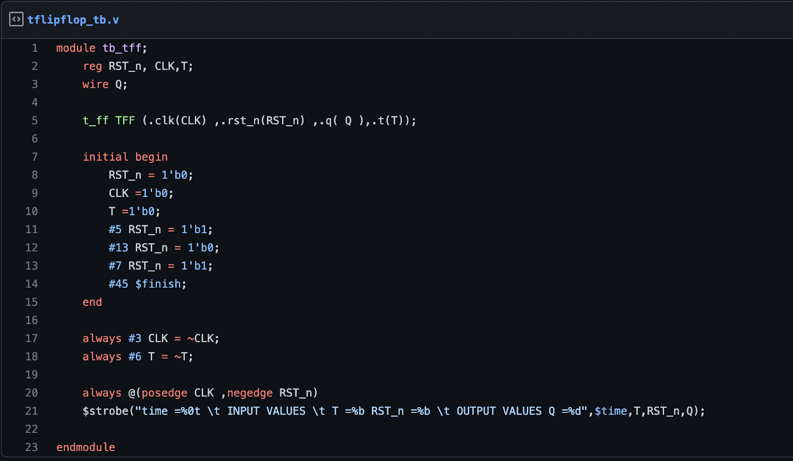
T-FlipFlop
Design File
module t_ff (
input clk,t,rst_n,
output reg q);

    always@(posedge clk ,negedge rst_n)
    begin
        if (!rst_n)
            q <= 1'b0;
        else if(t)
            q <= ~q;
        else
            q <= q;
    end

endmodule
Testbench File
module tb_tff;
    reg RST_n, CLK,T;
    wire Q;

    t_ff TFF (.clk(CLK) ,.rst_n(RST_n) ,.q( Q ),.t(T));

    initial begin
        RST_n = 1'b0;
        CLK =1'b0;
        T =1'b0;
        #5 RST_n = 1'b1;
        #13 RST_n = 1'b0;
        #7 RST_n = 1'b1;
        #45 $finish;
    end

    always #3 CLK = ~CLK;
    always #6 T = ~T;

    always @(posedge CLK ,negedge RST_n)
    $strobe("time =%0t \t INPUT VALUES \t T =%b RST_n =%b \t OUTPUT VALUES Q =%d",$time,T,RST_n,Q);

endmodule
3-bit Counter
Design File
module t_ff(
output reg q,
input t, rst_n, clk);

always @ (posedge clk or negedge rst_n)
    if (!rst_n) q <= 1'b0;
    else if (t) q <= ~q;

endmodule

//Standard counters are designed using either T or JK F/F.

module counter (
    output [2:0] q,
    input rst_n, clk);

    wire t2;

    t_ff ff0 ( q[0], 1'b1, rst_n, clk);
    t_ff ff1 ( q[1], q[0], rst_n, clk);
    t_ff ff2 ( q[2], t2,   rst_n, clk);
    and a1 (t2, q[0], q[1]);

endmodule
Testbench File
module tb_counter_3bit;
    reg clk,rst_n;
    wire [2:0] q;
    reg [2:0] count;

    counter CNTR (.clk(clk),.rst_n(rst_n),.q(q));

    initial begin
        clk <= 1'b0;
        forever #5 clk <= ~ clk;
    end

    initial
    begin
         rst_n <= 0;
         @(posedge clk);
         @(negedge clk);
         rst_n <= 1;
         repeat (10)   @(posedge clk);
         $finish;
    end

    //Below always block represents the 3-bit counter in behavior style.
    //Here it is used to generate reference output
    always @(posedge clk or negedge rst_n) begin
         if (!rst_n)
             count <= 0;
         else
             count <= (count + 1);
    end

    always @( q ) scoreboard(count);

    //Below task is used to compare reference and generated output. Similar to score board //in SV Test bench

    task scoreboard;
    input [2:0]count;
    input [2:0] q;
    begin
       if (count == q)
           $display ("time =%4t q = %3b count = %b match!-:)",
                                  $time, q, count);
       else
           $display ("time =%4t q = %3b count = %b <-- no match",
                                 $time, q, count);
    end
    endtask

endmodule