
Acoustic Filters – SAW and BAW Filters
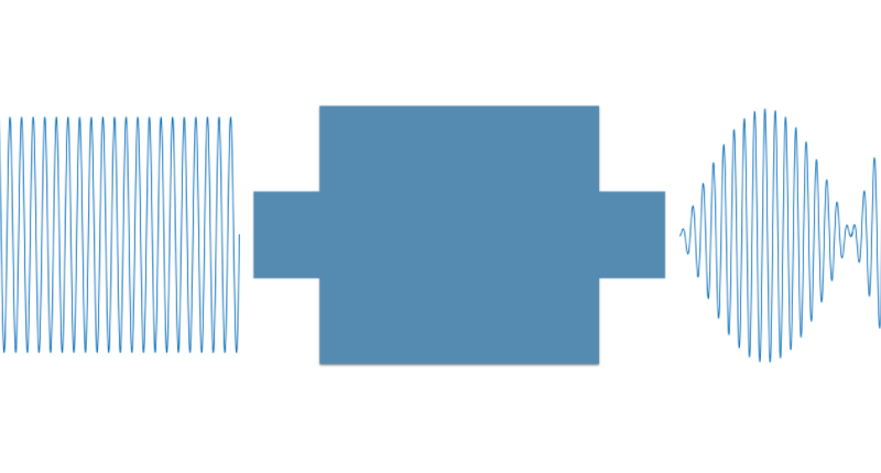
Filter Sampling
Acoustic filter technologies continue to the global transition to the latest radio networks. In acoustic filters (SAW & BAW), the waves are confined to create standing waves with extremely high-quality (high-Q) factors of several thousand. These high-Q resonances are the basis of the frequency selectivity and low loss that acoustic filters achieve.
In this article, you find out about surface acoustic wave (SAW) and bulk acoustic wave (BAW) filter technologies, which are used to solve many of today’s toughest filtering problems.
Table of Contents
SAW Filters
SAW filters combine low insertion loss with good rejection, can achieve broad bandwidths, and are a tiny fraction of the size of the traditional cavity and ceramic filters.
In a basic SAW filter, an electrical input signal is converted to an acoustic wave by interleaved metal interdigital transducers (IDTs) created on a piezoelectric substrate, such as quartz, lithium tantalite (LiTaO3), or lithium niobate (LiNbO3). Its slow velocity makes it possible to fit many wavelengths across the IDTs in a very small device.

A key advantage of SAW is its capability to optimally meet standard filter applications up to 1.9 GHz, including several standard bands such as GSM, CDMA, 3G, and some 4G bands.
SAW filters, however, have limitations. Above about 1 GHz, their selectivity declines; at about 2.5 GHz, the use of SAW is limited to applications with modest performance requirements. SAW is also very temperature sensitive. The stiffness of the substrate material tends to decrease at higher temperatures and acoustic velocity diminishes.
BAW Filters
BAW filters generally deliver superior performance (higher Q) with lower insertion loss at higher frequency levels. With BAW technology, it is possible to create narrowband filters with exceptionally steep filter skirts and excellent rejection.
BAW can address frequencies up to 6 GHz and is used for many of the new LTE bands above 1.9 GHz. BAW filter size also decreases with higher frequencies, which makes these filters ideal for the most demanding 3G and 4G applications. In addition, BAW design is far less sensitive to temperature variation even at broad bandwidths.
Unlike SAW filters, the acoustic wave in a BAW filter propagates vertically (see Figure 2-2). In a BAW resonator using a quartz crystal as the substrate, metal patches on the top and bottom sides of the quartz excite the acoustic waves, which bounce from the top to the bottom surface to form a standing acoustic wave.
The frequency at which resonance occurs is determined by the thickness of the slab and the mass of the electrodes. At the high frequencies in which BAW filters are effective, the piezo layer must be only micrometers thick, requiring the resonator structure to be made using thin-film deposition and micro-machining on a carrier substrate.

BAW excels in applications where the uplink and downlink separation is minimal and when attenuation is required in tightly packed adjacent bands. Although BAW inherently has about half the temperature-drift performance of standard SAW, there are cases where this improvement is not sufficient.


